H. G. Thum (DK2KA)
If you want to create detailed images of astronomical radio sources, antennas with high angular resolution are needed. High angular resolution can only be achieved with large mirrors, but there are limits to the mechanical implementation. The limit for movable mirrors is a diameter of 100 m, and fixed mirrors can be built up to 300 m. If you want to achieve higher angular resolution, you can only do so by combining several mirrors (interferometry).
The largest mirror spacing (baseline) would be the diameter of the Earth. But if that is not enough, then satellites must be included in the measurement. For good image representation, not only large antenna spacings should be taken, but also small spacings of 100 meters. If this is not done, the images will be blurred. At least 5 antennas and/or 7 baselines are needed to create an image.
Data must be collected at all receiving locations with frequency stability and the same clock frequency. This is achieved through hydrogen maser as a clock source.
We don’t have all of this! – But!

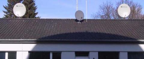
We have the interferometer on the Stockert Sonnenhaus!
System data
Mirror size: 1.2 m – Type: offset mirror
Active area: 0.85 m² – Gain approx. 41 dB
Antenna angle: 1.4° – Finger angle: 0.16° @10.5 GHz
Polarization: Horizontal and vertical
Number of mirrors: 2 – Baseline: 10.4 meters
Fixed south orientation, elevation range: 9° to 86° (Dec. -32° to 46°)
Operating range: 10.4 GHz to 12.4 GHz – Reference frequency: 25 MHz
Current measurement frequency below geostationary TV satellite channels (10.44 GHz)
Since we have the two receiving antennas at one location, we can distribute our reference frequency over coaxial cable. Since we measure locally and not in a network, there are not such high requirements for the stability of the time clock for the measurement. When only two mirrors are combined into an interferometer, images cannot be generated, but an increase in sensitivity is achieved. By combining antennas, the two received signals are superimposed.
This superposition is always a very specific frequency determined by the receiver frequency, antenna spacing, declination angle, and object velocity. This frequency (finger frequency) can be searched for in the noise of the total signal with a frequency analysis program (FFT). At a declination angle (Dec) of 0 degrees, this frequency is highest and is 0.025 Hz in our setup. If the declination angle is changed, the frequency decreases. The polar star at a Dec. of +90 degrees stands still, so the frequency is 0 Hz.
The achieved receiving sensitivity exceeded expectations and could be further increased by multiple measurements of an object. Further improvement can be achieved by simultaneously capturing horizontal and vertical polarization.
The basic sensitivity is determined by the diameter of the antennas (receiving area). Angular resolution and finger frequency increase with the greater distance between the two antennas. A good compromise is when the distance between the antennas corresponds to 10 times the diameter of the antennas.
For our 1.2-meter antennas, the frequency used of 10.4 GHz, and a distance of over 10 meters, an angular resolution of about one degree is obtained.
